


The present page presents the benefits of TRUE AMPLITUDE seismic reflection from VSPs for the geologist interpreter. Additionally, a method for the detection and quantification of INTERNAL OR INTERBED MULTIPLE REFLECTIONS from the VSP is exposed on a near 1D field case study, defining the physical limitations of surface seismic, in order to warn the interpreter and the surface seismic processing geophysicist.
Around 75% of commercial borehole seismic operations are zero-offset vertical seismic profiles (VSPs), or “Rig-source VSPs”.
The VSP method involves recording the seismic signal by a sensor located in a borehole, from which an incident downgoing seismic signal generated on surface is followed by upgoing signals reflected below the borehole sensor.
A- Producing VSP reflections in TRUE AMPLITUDE
It looks surprisingly easy and robust to extract the amplitude and phase of seismic reflection when processing a VSP dataset , at least in the corridor stack domain and in the limited frequency range of the incident downgoing signal reduced to a desired zero phase pulse by the common “wave shaping”, or “signature” deconvolution process commonly used by all industrial and academic VSP processing geophysicists since its first introduction by seismic pioneer Nigel Allistair Anstey, through his founding 1976 patent GB 1 569 581-ANSTEY.
Actually, the digital deconvolution of VSP’s was applied immediately after VSP data started to be field recorded in digital form, around 1975. The famous article Reflections on Amplitude in surface seismic was previously published in 1971 by the same geophysicist N.A. Anstey with his colleague O’ Doherty R.F.
The VSP acquisition and processing procedures initiated by N.A. Anstey in his patent have been improved, notably by using highly repeatable vibrator trucks for recording onshore VSPs, and by stable airgun sources for offshore VSPs.
At processing, highly precise algorithms are used today, although the order of VSP processing operations can be revised: for instance, the geometrical spreading compensation operation should preferably be applied BEFORE wave field separation, and AFTER deconvolution, in order to correctly compensate for the propagation effects on a pulse VSP earth response dataset. The processing fidelity plays a major role on the quality and reliability of the seismic reflections in the VSP processing results. A true amplitude VSP processing procedure is described in US patent 2003/0086335 A1 by Naville, C., illustrated by a 1D VSP field case study. In order to further simplify the common VSP processing procedures to obtain true amplitude VSP reflections, an alternative processing route is proposed as follows:
- Deconvolution is applied FIRST in the true amplitude VSP processing procedure, using an appropriately short to medium long downgoing wavelet, about 600ms maximum, previously extracted after normalizing the picked direct arrival, PRIOR to the amplitude correction of spherical divergence which can be correctly applied only to an Earth pulse response dataset: as a matter of fact, most of the downgoing pegleg wavetrain generation occurs in the heterogeneous shallow near surface zone, far away from downhole VSP sensor positions. Moreover, one has to keep in mind that in a horizontally stratified medium of geological layers of differing velocities, the spherical spreading function of the reflected VSP arrivals in a zero offset VSP recorded in a vertical well is usually DIFFERENT from the spherical spreading function of the direct arrival at the same propagation time on a deeper VSP station. This observation justifies operating a “ time signal compression” of the downgoing wavetrain by signature deconvolution as the FIRST VSP processing operation; in the same manner, and for the same reasons, geophysicists correlate the raw seismic signals emitted by vibrators trucks as the first signal processing operation. Thus, in order keep intact the relative amplitudes of reflected events to the direct arrivals on the same wiggle signal of any given VSP station, the signature deconvolution is applied to the raw un-separated VSP data, resulting into the pulse earth VSP response on which the transmission effects can be correctly compensated; moreover, this procedure simplifies the processing procedure and minimizes the risk of amplitude mismanagement of separated wavefield files during the processing course, especially when the full processing of oriented 3-Component VSP data is undertaken.
- After signature deconvolution, the direct arrival is normalized to the same amplitude level for ALL depths, in the common frequency range of the VSP dataset, or in several different frequency ranges if the attenuation of high frequencies becomes notoriously different from the attenuation of lower frequencies. By definition, the amplitude normalization of the deconvolved direct arrival pulse compensates for all the propagation effects of transmission, attenuation, geometrical spreading, between the surface source and the considered downhole VSP receiver, as long as a single raypath can be considered.
- The spherical divergence function versus two way time can be preferably derived from the first arrival VSP times, as illustrated on slide 6 of the OA02-More info from VSP presentation file: by doing so, no trial and error amplitude recovery test associated with a visual appreciation is necessary anymore prior to VSP processing as the quantification of the spherical divergence compensation is constrained by the VSP dataset itself. Where the geological structure can be assimilated to a 1 Dimension stratified medium, the spherical divergence of VSP reflections can be derived from the VSP first arrival times, as explained in US patent 2003/0086335 A1. Needless to say, the spherical divergence function versus twt derived from VSP is valid for processing the surface seismic data recorded in the borehole vicinity, which allows for estimating the importance of other seismic signal attenuation factors.
- The spherical divergence gain compensation can then be applied on the deconvolved full wavefield VSP earth response before wave separation, then the first arrival pulse is normalized again. After elimination of the normalized deconvolved direct arrival pulse using appropriate velocity filters, the seismic reflections are set in two way times and a layer to layer intrinsic attenuation compensation ( transmission + scattering effects) can eventually be applied, possibly varying versus frequency bands.
- The seismic reflections contained within the corridor stack domain, commonly restricted to a 50-100ms time window after direct arrival, barely needs any geometrical spreading compensation to restitute the true reflection amplitudes. For instance if the peak value of the direct deconvolved VSP arrival is normalized to the value of 100, the reflection amplitudes can be read directly as percentage reflection amplitudes, starting on the VSP corridor stack.
- A verification of the true amplitude VSP reflections has been carried out on a modeled VSP dataset: a true amplitude Zero-offset VSP (ZVSP) processing procedure was applied to the results of ZVSP dataset computed by a 2D acoustic model without attenuation in a horizontally layered medium, with a zero-offset point source at surface, and receivers in a vertical well. The figure shown in slide 20 of the True Amplitude 3C VSP method presentation shows different versions of the true amplitude VSP Corridor Stack (VCS) to be compared with the true amplitude synthetic seismogram computed from the same initial layered model, from left to right:
a) VCS without any amplitude compensation of reflection amplitudes;
b) VCS with only spherical divergence correction;
c) VCS with spherical divergence and transmission corrections from first arrival time.
d) True amplitude synthetic seismogram from sonic and density 1D logs of the layered VSP model, convolved with the zero phase pulse obtained after deconvolution of the downgoing VSP signature.
e) Initial impedance 1D model.
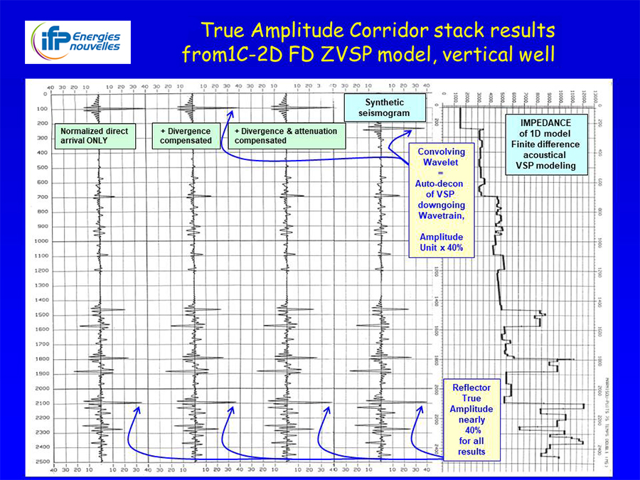
On the above figure, the peak amplitude of the zero phase pulse has been reduced to 40% in order to facilitate the comparison with the deep reflection amplitudes.
One can appreciate the reliability of the True amplitude VSP processing procedure as the fully compensated reflection VSP corridor stack in track c) is near identical to the synthetic seismogram in track d), in spite of totally different processing routes. When no amplitude correction is applied, on VCS-track a), the reflection amplitudes are lower by only 10% than the true amplitudes, although the 100ms time window retained for the corridor stack domain was quite large, and the reflection amplitudes do not change significantly relatively to each other.
The above example indicates that the industrial practice of synthetic seismogram construction, from sonic log calibrated with VSP times, and preferably with density log, can easily yield true amplitude modeled reflections within the frequency band associated with the convolutional wavelet, to be compared with the true amplitude VSP corridor stack in a similar frequency band; thus, the seismic reflection amplitudes from both borehole seismic methods can be analyzed and interpreted with higher accuracy and pertinence.
B- Detection of INTERBED MULTIPLES from VSP; case study of multiple elimination on a field VSP
The following presentation document : Internal multiple from VSP-Overview explains the generation principle of seismic interbed multiples between two horizontal reflectors on a VSP dataset recorded in a vertical well with a surface source located near the wellhead, and the preprocessing route for the fine detection and characterization of interbed multiples from the downgoing VSP wavetrain.
The surface seismic imaging case study of a 2D line combined with a VSP located on the line is illustrated in the following presentation document: IFPEN-TAQA-Canada_internal multiple from VSP. A dedicated processing analysis of VSP data evidenced TWO coinciding observations about the seismic propagation through and surrounding a coalbed:
i) drastic attenuation of high seismic frequencies above 60Hz associated with a substantial phase rotation of the seismic signal transmitted through a 12m thick coalbed,
and ii) interbed multiples between top of coalbed and strong reflectors located above the coalbed; curiously, interbed multiples expected between base of coalbed and strong underlying reflectors are not clearly observed…
After detection and quantification, the complex interbed multiples between top of coalbed and strong reflectors above it have been tentatively eliminated using an innovative deterministic deconvolution approach on the VSP dataset, showing a net success for the true reflector response recovery of the reflectors located immediately beneath the coalbed, and a mitigated success in the deeper targeted interval.
In addition, the observations derived from fine VSP data analysis have been used to design a dedicated anti-multiple processing procedure for surface seismic data, enabling a substantial mitigation of the damaging effects induced by the presence of a coalbed in the lithological column, which drastically distorts the seismic image of reflectors in the underlying reservoir interval; however, high frequencies above 60Hz are definitely lost in surface seismic for all the targeted reflections underlying the coalbed.
The tested application consists in a two-gate predictive or spiking deconvolution, with operators independently computed above and below the top coalbed reflection; this procedure would be preferably improved by a modern surface consistency feature. It constitutes an innovative anti-interbed multiple procedure at prestack stage; although the processing adjustments and time gate guidance is implemented in most of the industrial seismic processing packages, the design of the different time computation windows can deeply impact the quality of the end seismic image. Incidentally, these conclusions are very similar to the ones obtained independently in the same time period around 1996 by Craig A. Coulombe and D. Neil Bird in their borehole seismic study in a well located West of Edmonton, entitled: Transmission filtering by high-amplitude reflection coefficients.
Using the true amplitude VSP corridor stack as the seismic response of the subsurface in a gently dipping structural context is a reliable manner to guide, check and confirm the technical soundness of the surface seismic processing results. The transmission operators computed from the downgoing VSP wavetrain exhibit accurately the frequency losses and the complex interbed multiples associated with a mix-phase rotation, however locally to the well. Therefore, the surface seismic deconvolution parameters must be carefully adapted to the dataset to be processed, knowing that the geometrical and physical characteristics of the coalbeds responsible for the phase distortion and transmission losses may vary laterally to the well. Unfortunately, the downgoing wave train of VSP’s is not thoroughly studied by the VSP processing industry on one hand, and usually ignored by the surface seismic processing industry on the other hand…
Lastly, the additional information derived from the VSP dataset processed in true amplitude manner is exposed in the following Appendix presentation file:
IFPEN-TAQA-Canada_VSP-appendices, including:
Appendix-A: borehole logs and true amplitude seismic seismograms compared with true amplitude VSP-Corridor Stack ; correction of the recorded gamma-gamma density log by the density value derived from the VSP-Corridor Stack and sonic log, mainly where large caves are present in the borehole, where the density log measurements are drastically altered, as observed in front of the coalbed and in the immediate proximity of a few caved layers.
In addition, the corrections of the measured density log made by interpolation over the caved depth interval are shown to be generally inaccurate. The above remarks indicate that the TRUE FORMATION DENSITY can be restituted in caved intervals by inverting a true amplitude VSP-Corridor Stack into impedance, then removing the effect of the sonic log value variations versus depth from the acoustical impedance inverted from VSP.
Appendix-B: ancillary information from the 3 components (3C) of the near zero offset VSP after orientation:
- S-wave time pick from converted P-S downgoing arrivals, S-wave velocity, Vp/Vs ratio, identification of an unmistakable long period seismic multiple generated between the coalbed and the ground surface,
- Identification of tube wave residual arrivals superimposed on the P-P reflected wavefield; the tube wave amplitude is amplified where the VSP tool is located in front of or close to large caves in the open hole, where the mechanical coupling of the VSP is loose. Nevertheless, these local alterations of the VSP tool response at a few sporadic VSP depth stations do not alter significantly the quality of the processed true amplitude VSP results, nor the interpretative conclusions.
Appendix-C: Frequency analysis of the P-P reflected true amplitude VSP Wavefield, using bandpass time filters on adjacent frequency bands. The images of filtered signals are displayed twice, first in true amplitude relatively to other frequency bands, and secondly after equalization, so as to facilitate the visual appreciation of signal amplitudes and Signal to Noise ratio (S/N) in each frequency band. This visual frequency analysis method reveals that the seismic reflections from underneath the coalbed, well identified on the VSP-Corridor Stack and on the logs, are TOTALLY attenuated above 60Hz when the VSP receiver tool is located above the coalbed. Consequently, the high frequencies above 60Hz are IRREMEDIABLY LOST for surface seismic for targets located below the coalbed, because of physical limitations of the seismic propagation through coal, independently from the recording technology and the field parameters, or from the geometrical survey design.
|
Scientific contact: |
References:
- 1976 patent GB 1 569 581-ANSTEY
Seismic delineation of oil and gas reservoirs using borehole geophones
N.A. Anstey
- Reflections on Amplitudes
1971-Geophysical Prospecting 19, P430-458,
O’Doherty , R.F., N.A. Anstey (Seiscom Limited)
>> https://onlinelibrary.wiley.com/doi/epdf/10.1111/j.1365-2478.1971.tb00610.x
- US patent 2003/0086335 A1
Method for absolute preserved amplitude processing of seismic well data
Charles Naville, Sylvain Serbutoviez
>> https://patents.google.com/patent/US20030086335A1/en
- OA02-More info from VSP
Presentation slides: extracting more information from rig source 3CVSPS, OA02, Fourth EAGE Workshop on Borehole Geophysics, 19-22November 2017, Abu Dhabi, UAE
C. Naville (IFPEN), A Rivet (CGG), V. Lesnikov (TOTAL)
- True Amplitude 3C VSP method
IFPEN presentation about 3C VSP processing route and interpretation ; November 2003, revised July 2020
Sylvain Serbutoviez, Charles Naville, Alexandre Throo, Josette Bruneau (IFPEN)
- Internal multiple from VSP-Overview: Dectection and quantification of interbed multiple from VSP downgoing wavetrain. principles
Charles Naville (IFPEN)
- IFPEN-TAQA-Canada internal multiple from VSP: IFPEN presentation about a case study of surface seismic and VSP altered by an interbed multiple created by a 12m thick coalbed and a strong transmission attenuation through the coalbed; November 2020
Charles Naville, Josette Bruneau (IFPEN)
- IFPEN-TAQA-Canada VSP-appendices: IFPEN presentation about additional information extracted from true amplitude processing of 3C VSP; November2020
Charles Naville, Josette Bruneau (IFPEN)
- Transmission filtering by high-amplitude reflection coefficients: Theory, practice, and processing considerations, CSEG Recorder, June 1997 | Vol. 22 N°. 06 | View issue
Craig A. Coulombe and D. Neil Bird (Chevron Canada Resources, Calgary)